Week 3
Computer Controlled Cutting.
Group Assignment.
The group assignment link can be found here
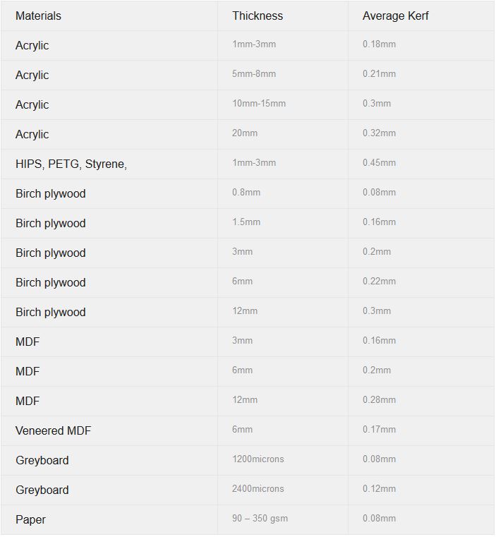
In our group assignment, we characterized the laser cutter’s properties. In particular, we deteremined a kerf of about 0.172mm, and additional offset of 0.1mm for snug fit but i would like to mention that in my particular case i re did design just becuase i wanted to do a snug fit joint using a plywood these settings couldn't fit so i kept trying different parameters till i found that with the material i have 0.5MM was the better choice.
This week’s assignment is centered around getting hands-on experience with the laser cutter, as well as the vinyl cutter.
Vinyl cutting
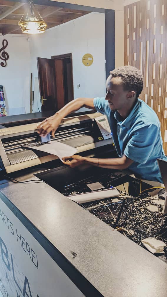
Our lab is equipped with a roland GX-24 vinyl cutter, To quickly try out the vinyl cutting process, I wanted to include a logo which is going to be a logo for my project. After connecting the cable to the computer to connect the software cutstudio that exports to the vinyl cutter, i inserted the sticker material
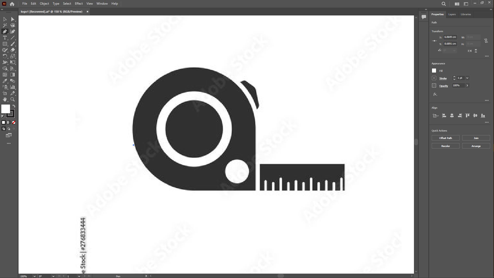
I had designed the logo in illustrator by tracing some pictures to help me get to the desired logo with that being said i used the sony logo in and another picture icon potraying a tape measure icon in order to get the symbols for the tape and the digital initials usally 1 0 to add to my logo. Now for this to be possible i used a pentool in illustrator in order to draw on top of the downloaded pictures; At first the picture has to be extended to the maximum by holding for tracing it with details using the pentool.
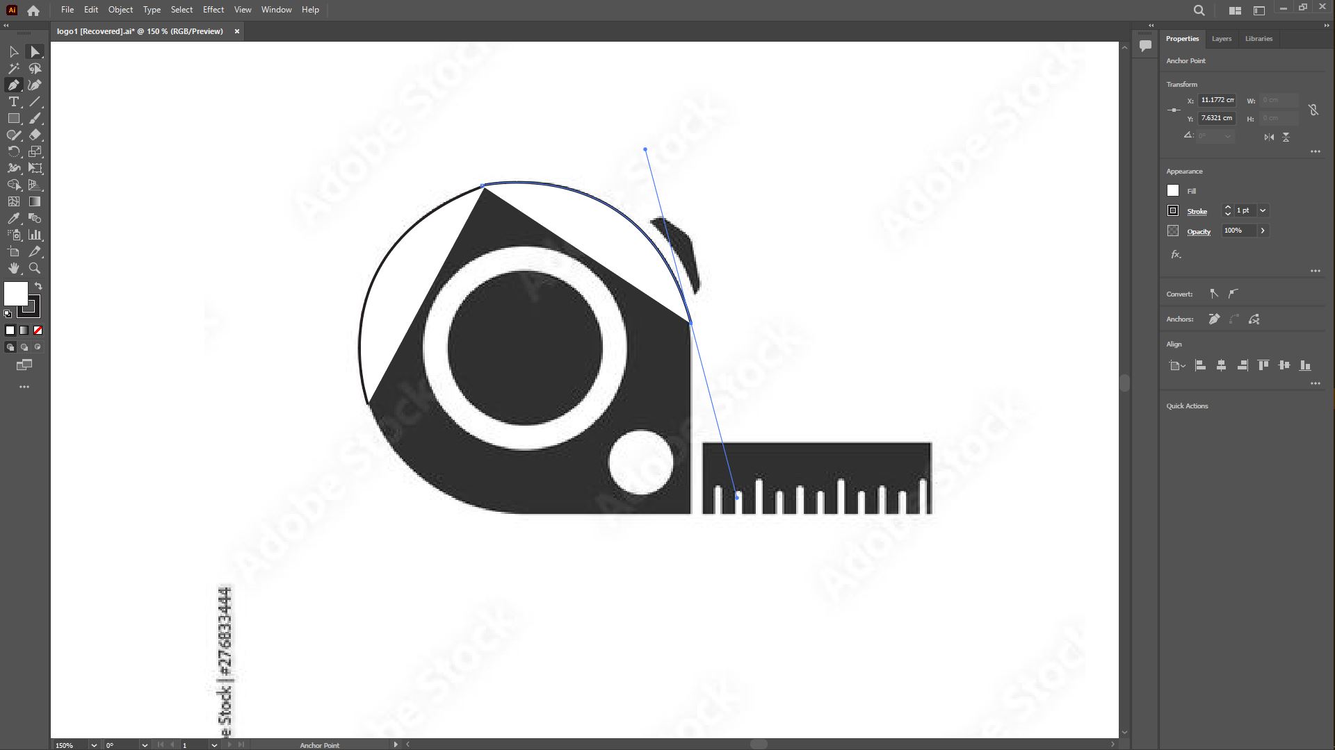
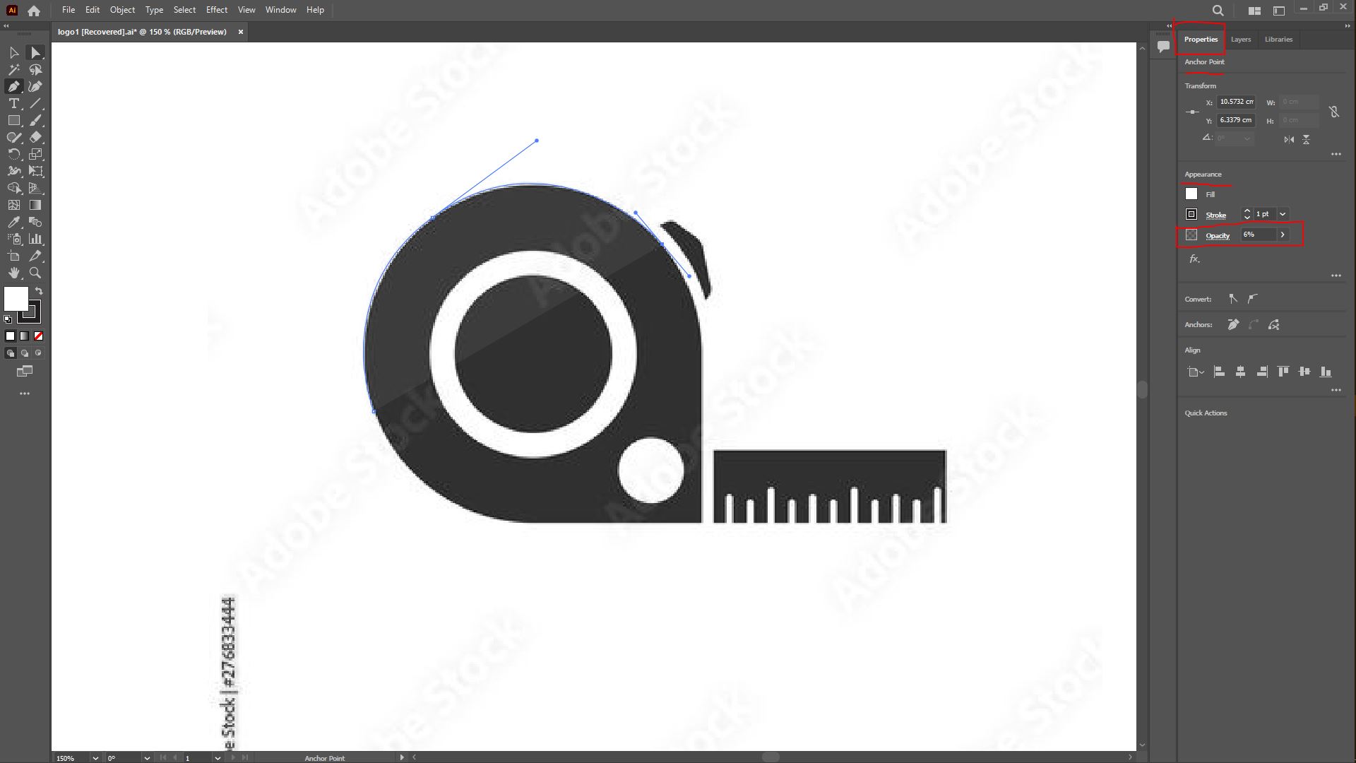
On this second picture going from left to right, you realize that the pentool while going around the picture tracing, it starts covering the initial picture preventing any further trace after closing the first trace as circle. So to resolve this, on the right panel of the illustrator of the workspace under the properties tab below anchor point and transform you will find appearances and one of its settings is opacity right below stroke and fill, by reducing its values to a 5_10%(i personally use 6%), it helps you trace with the picture clearly.
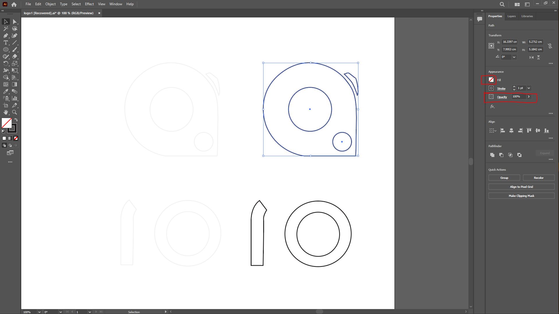
I used the same method for the sony logo but after tracing i deleted the picture so that i remain with the traced vectors but bearing in mind that we had set the opacity while tracing to 6% so the vectors on the left are what was left right after deleting the pictures we traced on, and on the right side are those with opacity set back to 100% but i also would like to mention what is known to be a good practice while tracing or doing vectors, so in graphic design we have a fill which is a color, pattern, or gradient inside an object. You can apply fills to open and closed objects and to faces of Live Paint groups. A stroke can be the visible outline of an object, a path, or the edge of a Live Paint group and so the good practice is to set the fill to a none meaning no color
The second pictures potrays 3 types of vectors: the first one has fill set at none color, the second vectors that i got by copy the first one by holding alt on a keyboard and then dragged to the right, after that i selected the vectors and gave them a black fill. The third vectors i selected the inner circles i gave them a white fill.
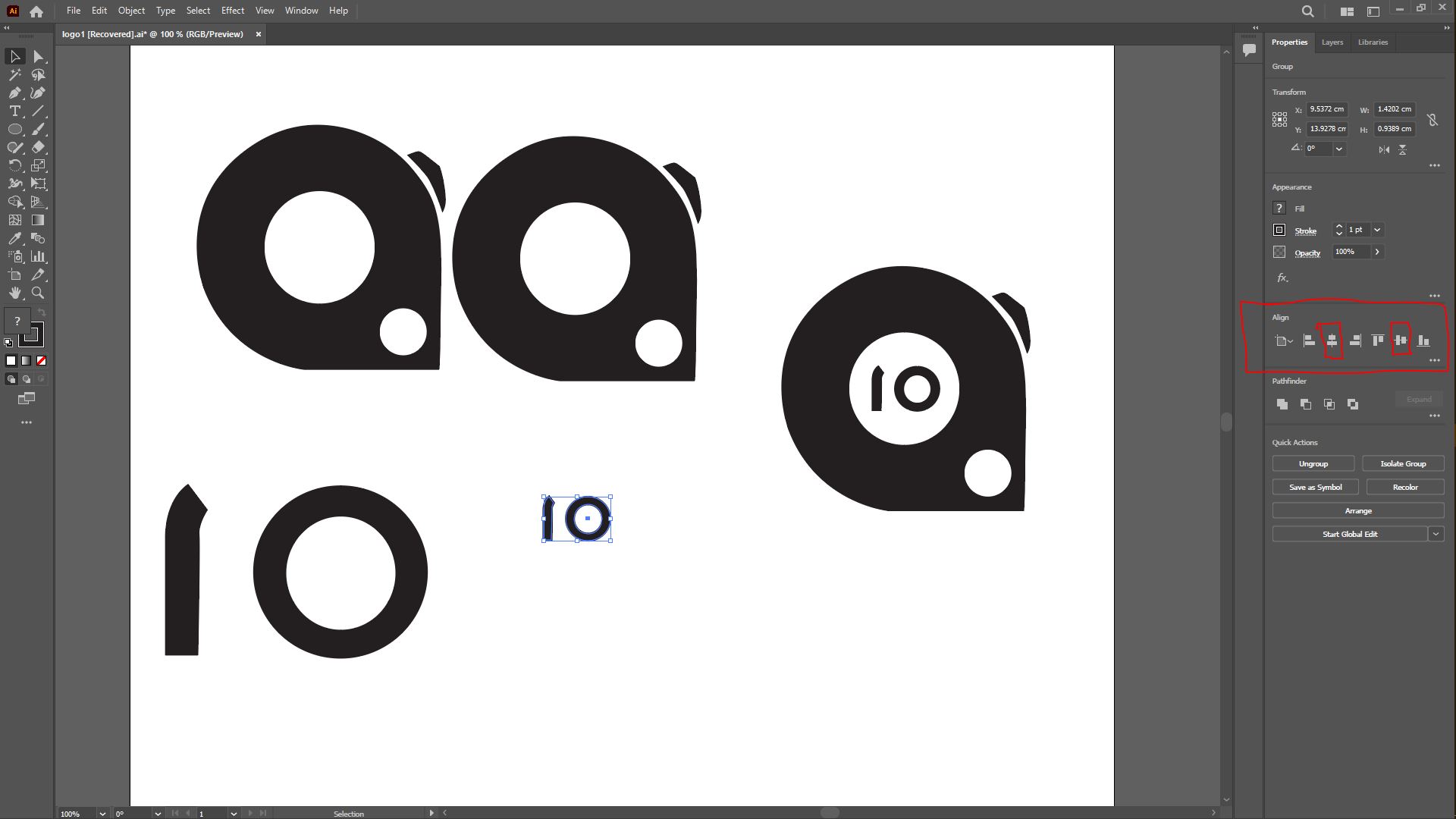
The third picture shows the following; i first selected each assemble of the traced and grouped them each by using a shortcut holding down ctrl+G (on windows), meaning the upper part of the logo on its own and the lower part alone too. I then minimized the digital initials using a shortcut of holding the shift (on windows) and draging in with the mouse from the bottom right corner until i reached the desired look, i then used a tool which is in the property bar right under appearances named Align in order to align the two groups center to center, so the marked second group of vectors are aligned horizontally by selecting both groups and and pressing the third icon under align in the property bar on the right side of the space which serves for aligning horizontally two selected groups of vectors or items. After that i copied again to the right, went on to press to the 6th icon under align which the purpose of aligning objects vertically and finally i made my logo by grouping together the two groups.

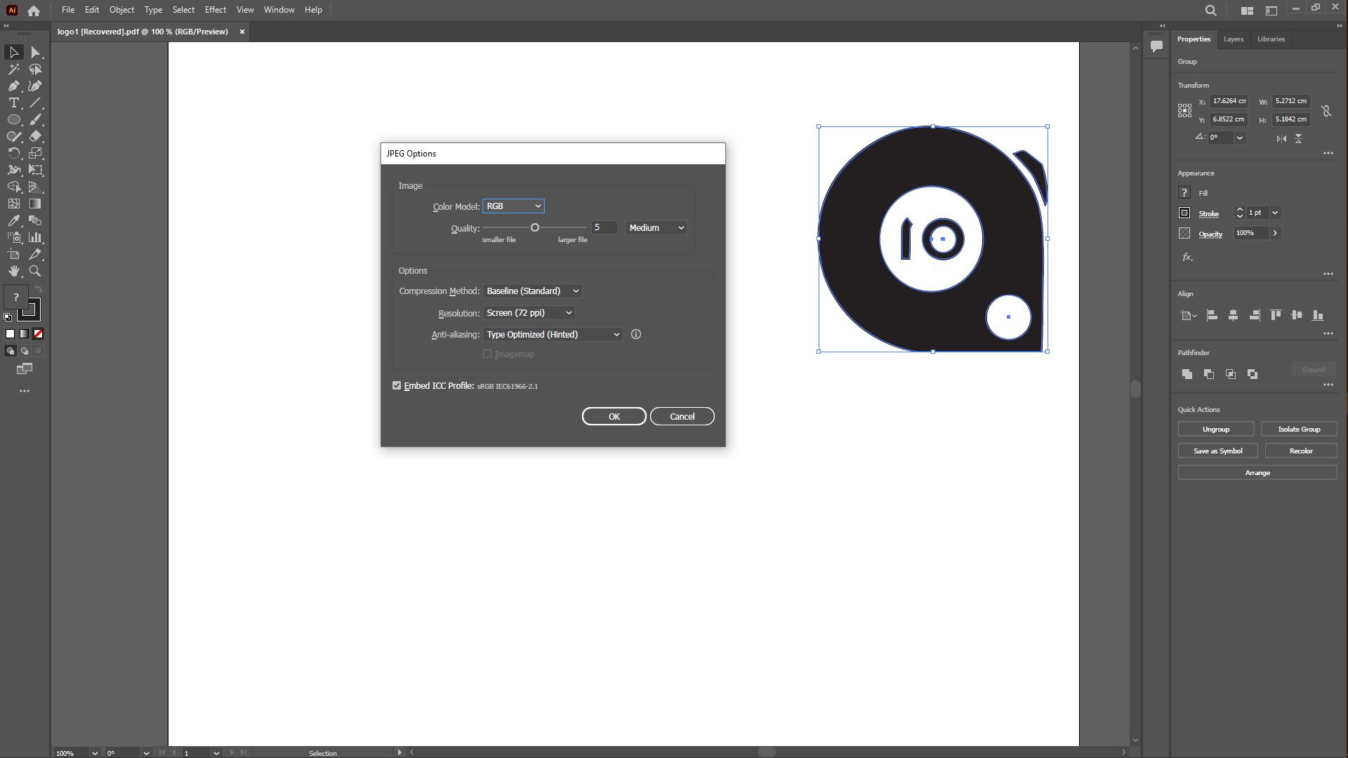
I proceeded with exporting the file as a JPG file because cut studio the software i will be using for vinyl cutter can work with a handfull types of files hence BMP, JPG, STX, AI and EPS(but older versions for the latter).


Installing cutstudio
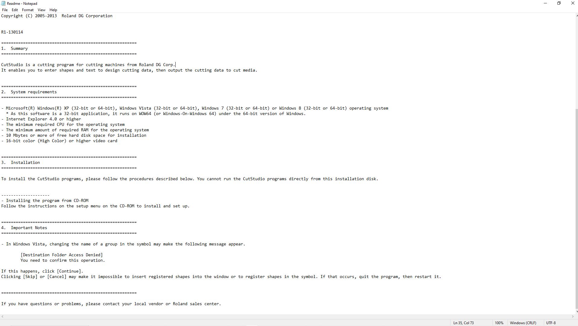
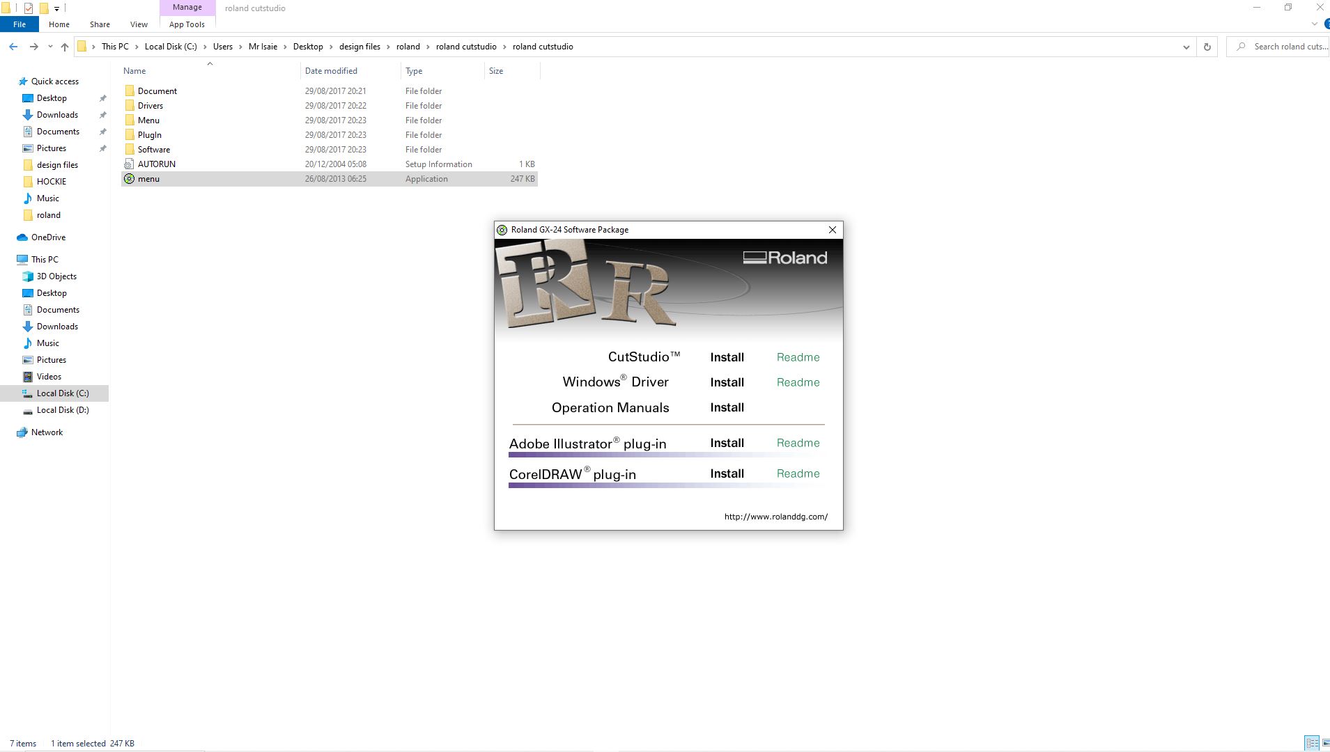
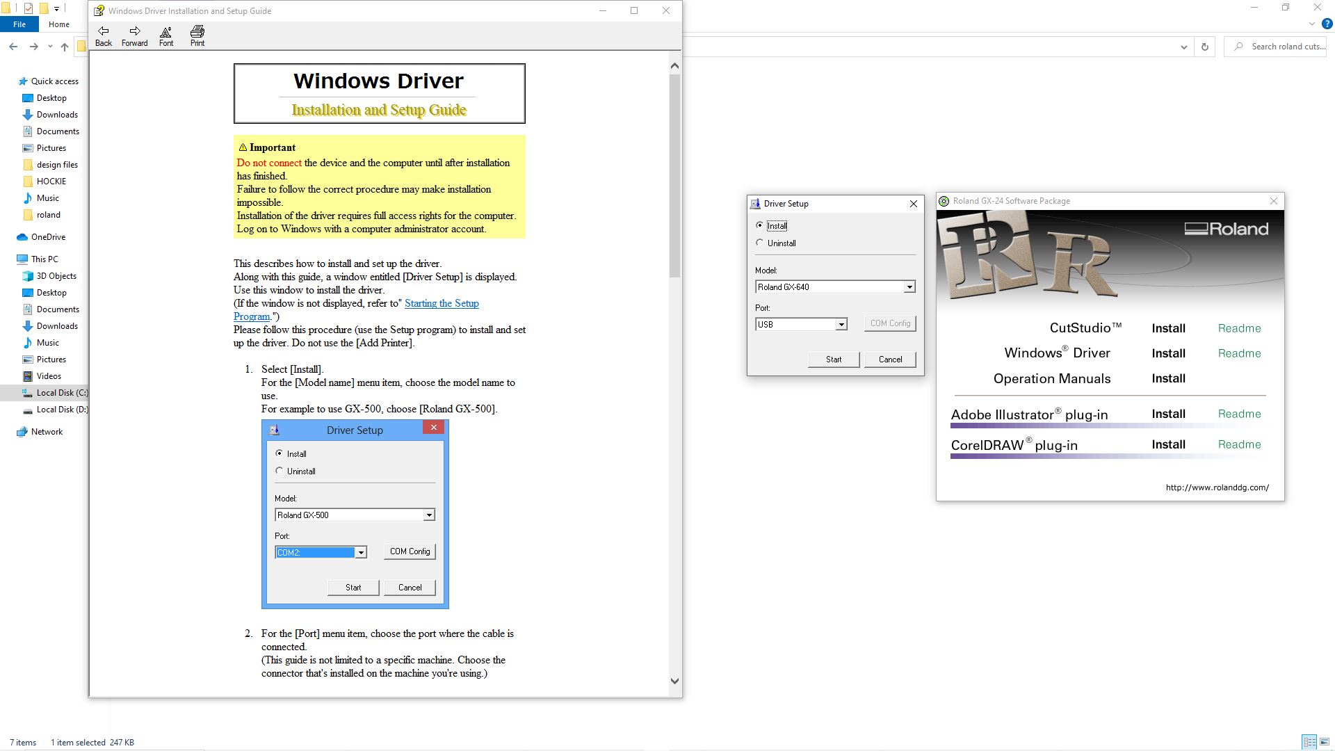
Regrding the software i was given via google drive the files by our lab instructor so i dowloaded the files to install to my computer here below is the process in pictures, usually the files are downloaded as a zipfile then after unziping the files i went on to read the set of instructions for installations found under software-cutsudio-open the readme file for instruction as potrayed in picture from left to right, After reading this readme note i clicked on menu which popped out the window that this second picture previews. As it was written in the readme file i had to first install the windows drivers for the cutstudio before installing cutstudio itself as seen in
Final installation of cutstudio

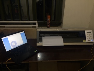
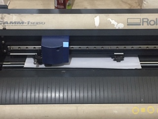
After connecting the cable to the computer to connect the software cutstudio that exports to the vinyl cutter which is roland GX-24, so after switching the machine on i connected thevinyl cutter to my pc via usb cable that connects the type b port of the vinyl cutter and the type A port of my pc; for the second picture you can see the piece of material in the vinyl cutter, so there's pinch roller on the left and the right and as a notice they must be aligned vertically with the white mark on top of it on this picture, and so basically pinch rollers are used for two roles one is for providing proximities in which the tool cutting carriage operates in and also to hold down the different types of materials ( and for them to hold the piecedown there's a clamp for push and pull on the the rightback of the machine) and easing the movement of the material back and forth that are used on the vinyl cutter being, sheet, roll and piece regarding size, in this case mine is a piece because its a small type of material. On the third picture the details of the size of that piece of material

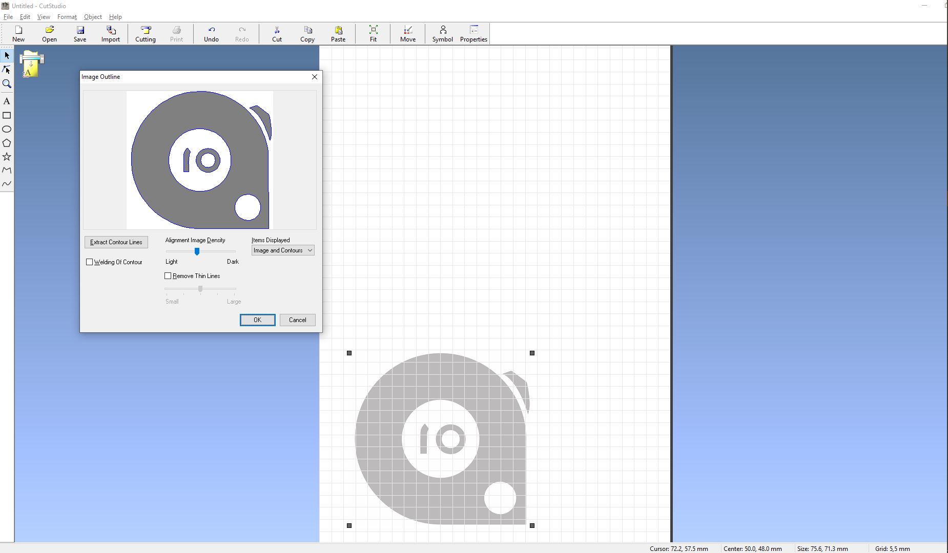
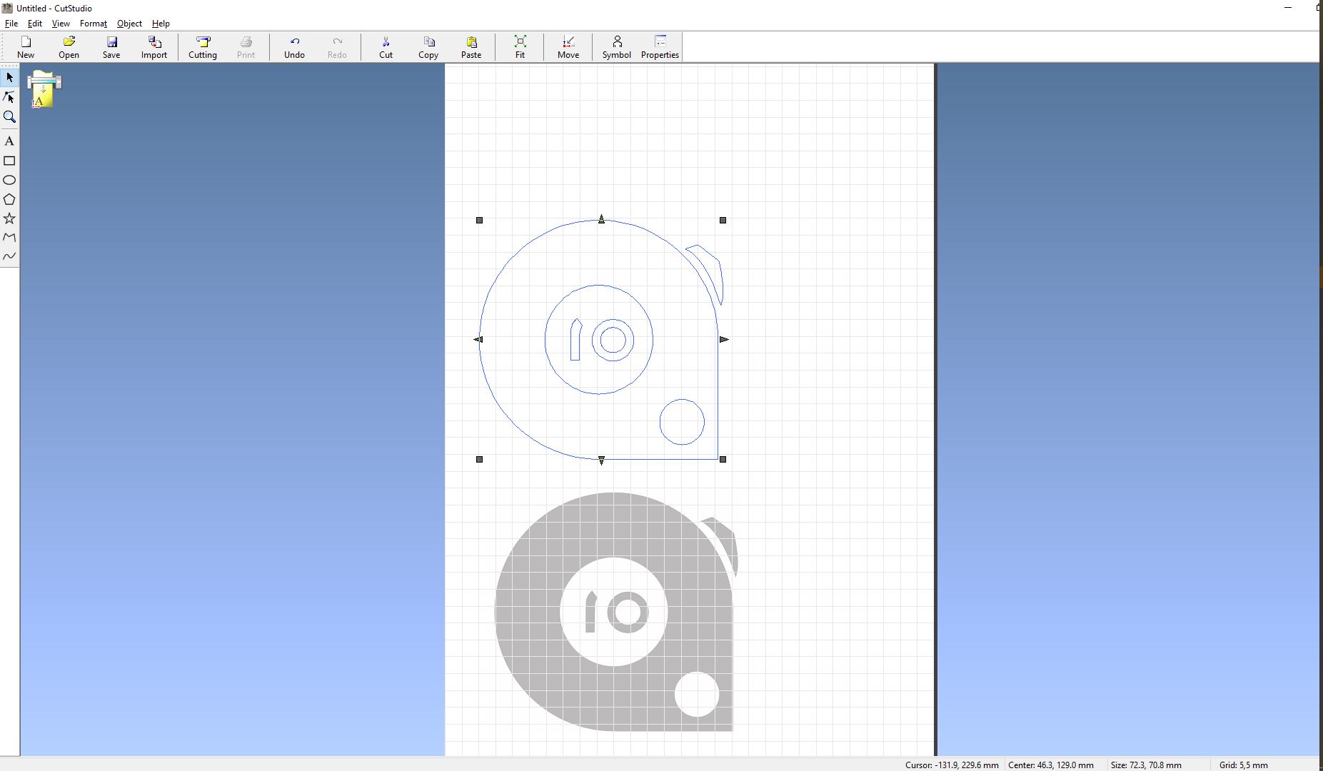
After opening cutstudio, I placed the design in the bottom left corner. Note that I had saved the file as a JPG format first. i clicked on file in the upper left corner then clicked on cutting set up which opened the window to connect the vinyl cutter with my computer, so on the window you click on where there's name/series of the machine you have, after adding it you click on properties which opens up up another window with size of the cutting area and the units in which you wish to be working into, so here you click on get from machine so that the accounted size of the piec of material be the same as that you have in the software so then after clicking on get from machine, it automatically sets the size thats in the machine in the software then you click ok and then click ok on the first window too After that i right clicked on the selected imported file to get to image outline which opens its window, then click on extract contour lines then ok. We do this so we can have a vectrorize file that the machine is going to cut after you deleter the picture and remain with the extracted countour lines and then click on cutting above in the options bar and then the machine starts cutting.

I used a regular sticker paper, with the following settings :
- offset: 0.250mm
- Force: 110gf
- Speed: 20cm/S
- Penforce: +2
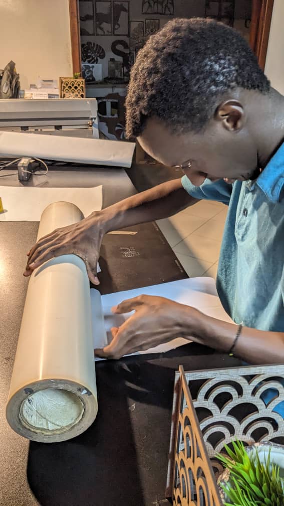
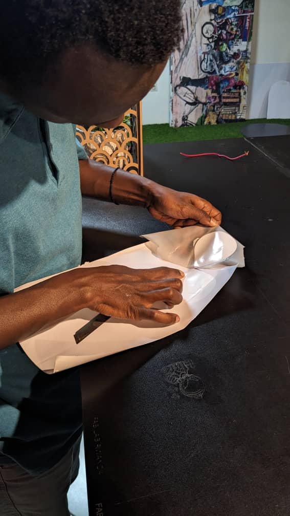
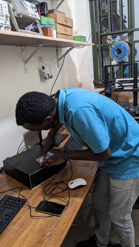
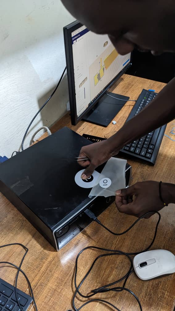
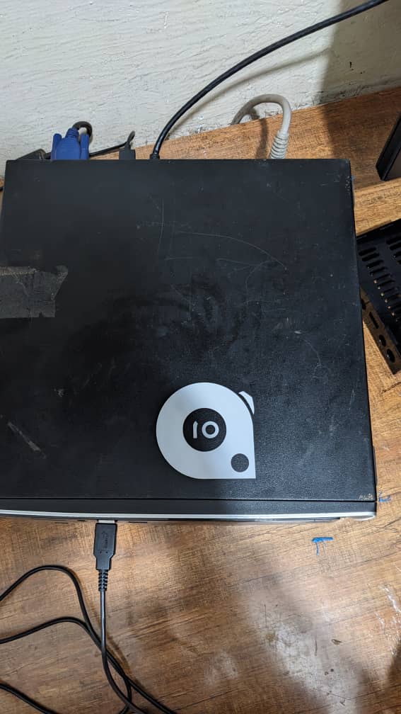
after cutting i pushed the clamp back to release the înch rollers holding down the piece of material, so i pull it out then i layed the Rtape clear choice on it to stick out the cut out part alone then placed it on the surface i wanted to layer it which in this case is the cpu of my working station then i peeled off the Rtape clear choice, but by peeling off i made sure to hold down the cut part that supposed to be the stickers and let the Rtape clear choice peel off the unwanted material and so below the described process is in pictures going from left to right
Laser cutting: construction kit
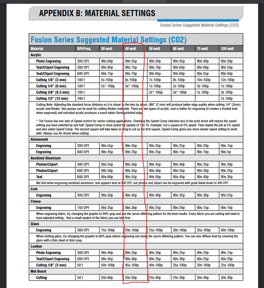
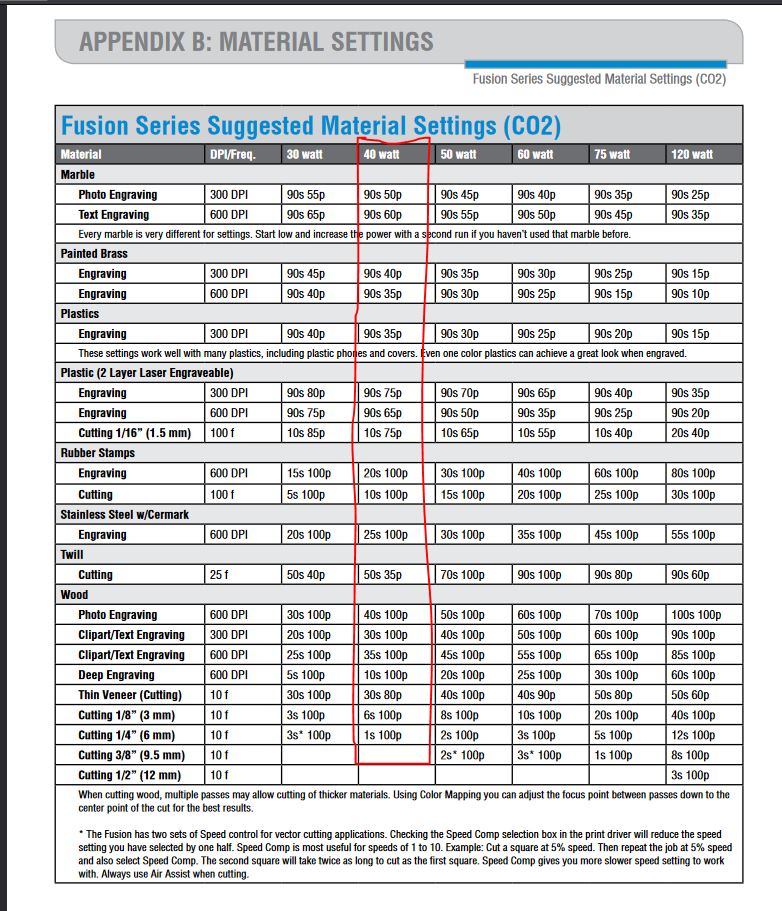
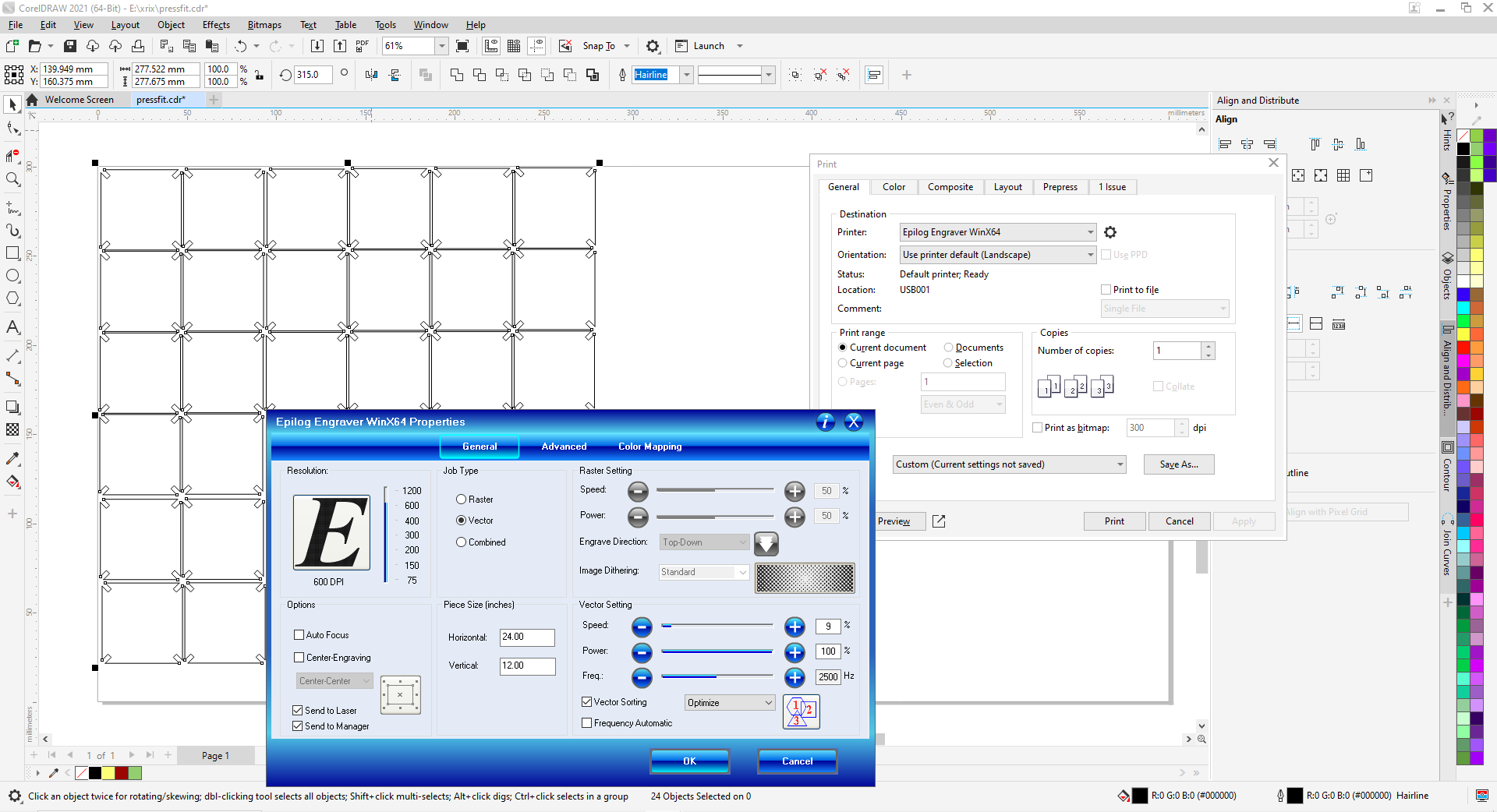
Our lab is equipped with Epilog Fusion CO2 laser 40watts with a bed size of 24″ x 12″ (610 x 305 mm), For power and speed, the Computer or manually control speed and power in 1% increments to 100%. Vector color mapping links speed, power and focus to any RGB color with a user controlled from 75 to 1200 dpi.
For power speed and rate
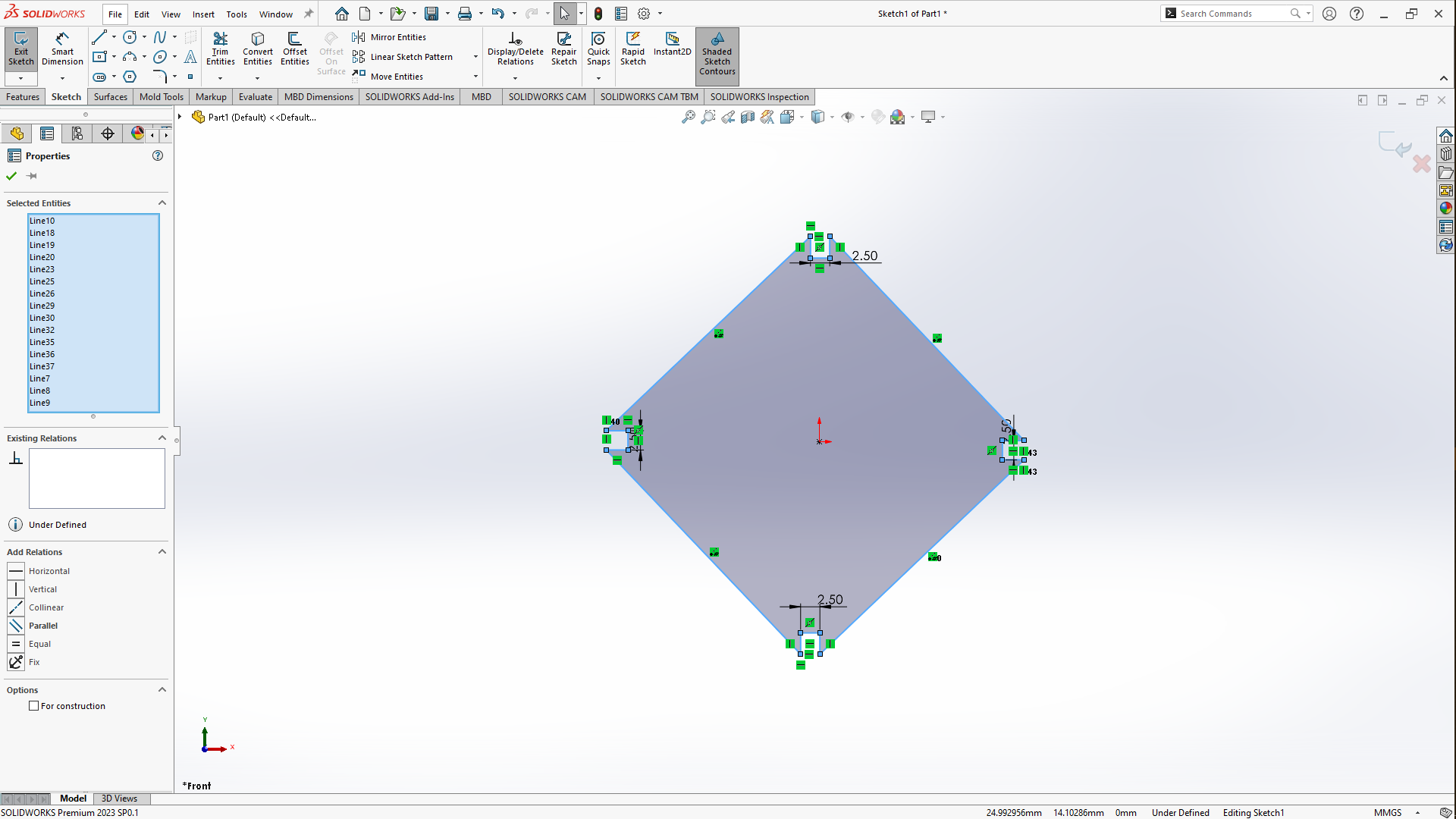
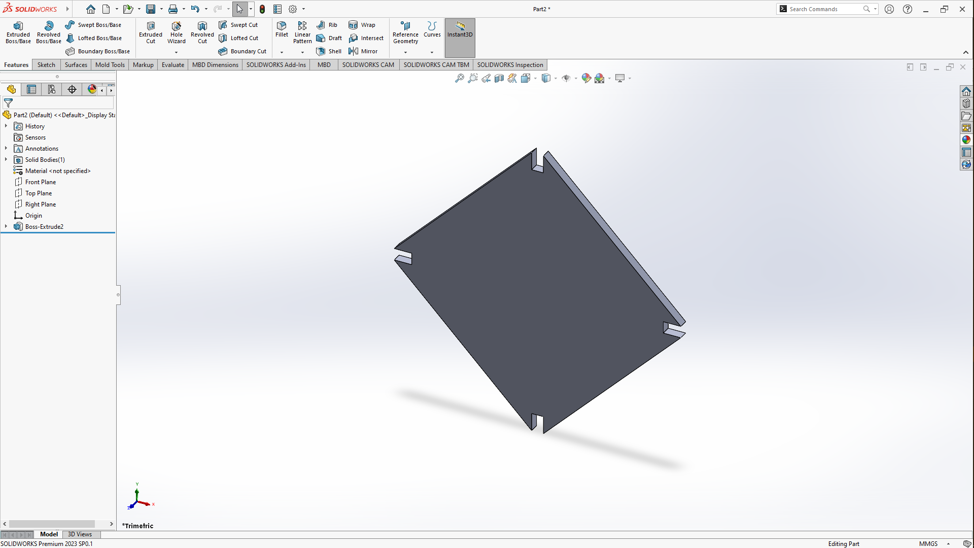
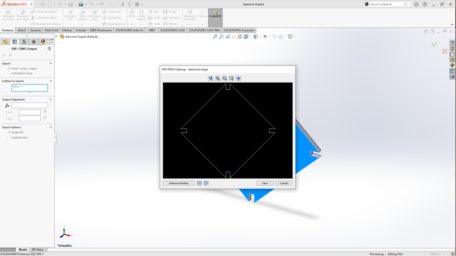
I started by drawing a simple square of 45mm by 45mm using a 3 Point Rectangle feature in solidworks by selecting the Front plane then the 3 point rectangle, then i added a small rectangle of 2.5mm by 5mm then i multiplied it to 4 rectengles using the mirror entities and the two crossed construction line parameters, added rectangle to each corner in order to make up for the joints to open the corners so that pieces fit each other then i used the Trim feature in the commands manager, then i saved the file as a DXF which brings you back to solidworks here you'll select the Faces/Loops/Edges then you click ok to a save a DXF file to use with coreldraw while cutting the pieces. Below are the pictures of the process:
As it was potrayed above in the paper about the kerf of our lab laser cutter machine which i found on some of the fabacademy alumnis's page. So the kerf for the material i had used(plywood) is 0.28mm which i came to realise that its more like 0.5MM through different testing on my ending whichlead to altering the design and is why i used the 2.5MM as the width of the joint in solidworks instead instead of using the normal 3MM thickness hence leaving the 0.5MM for the joints to fit.
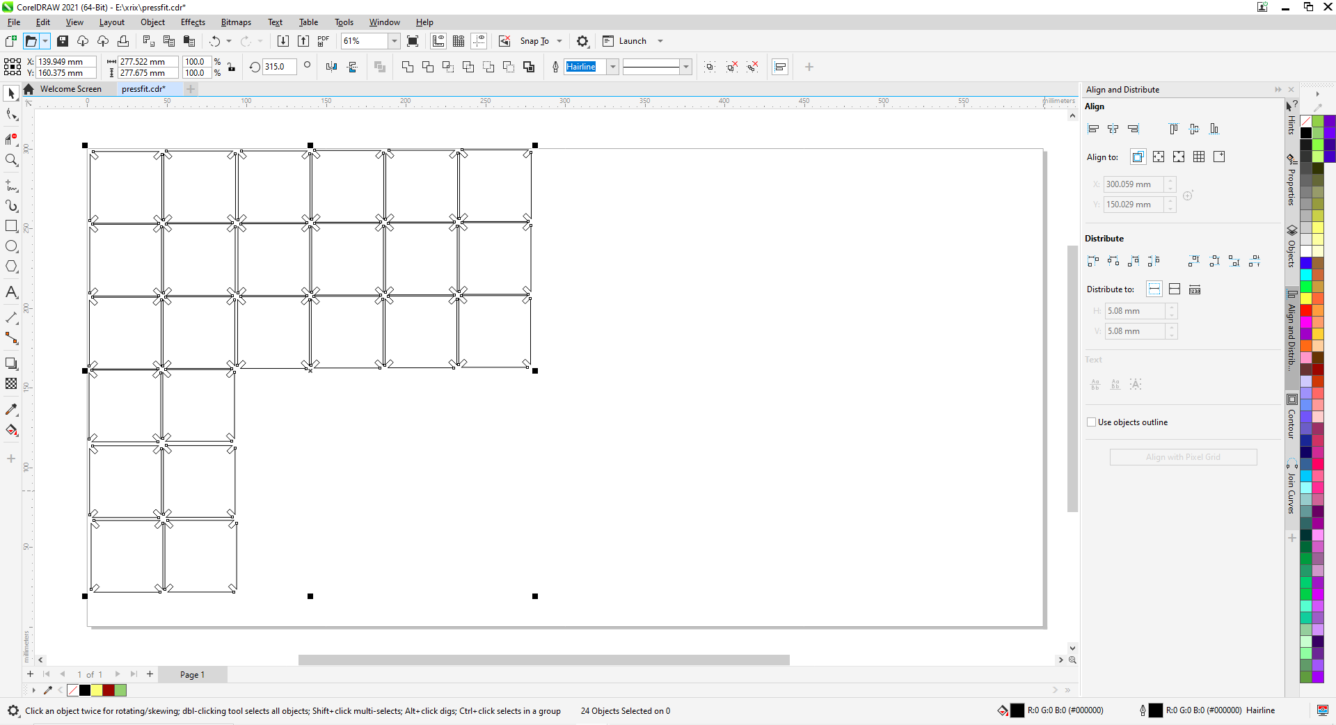
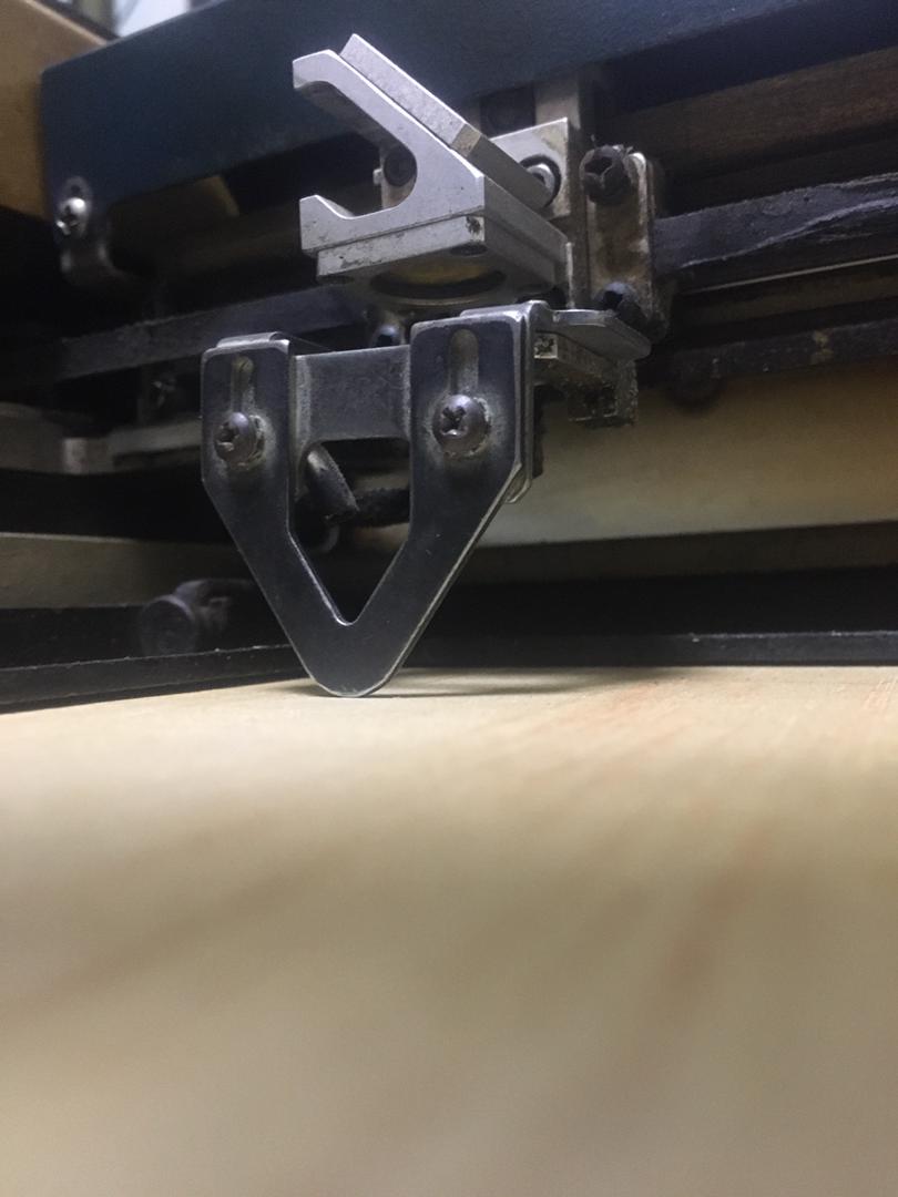
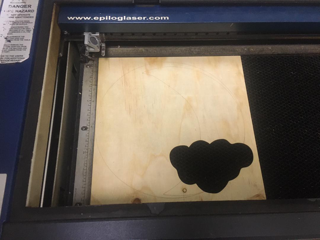
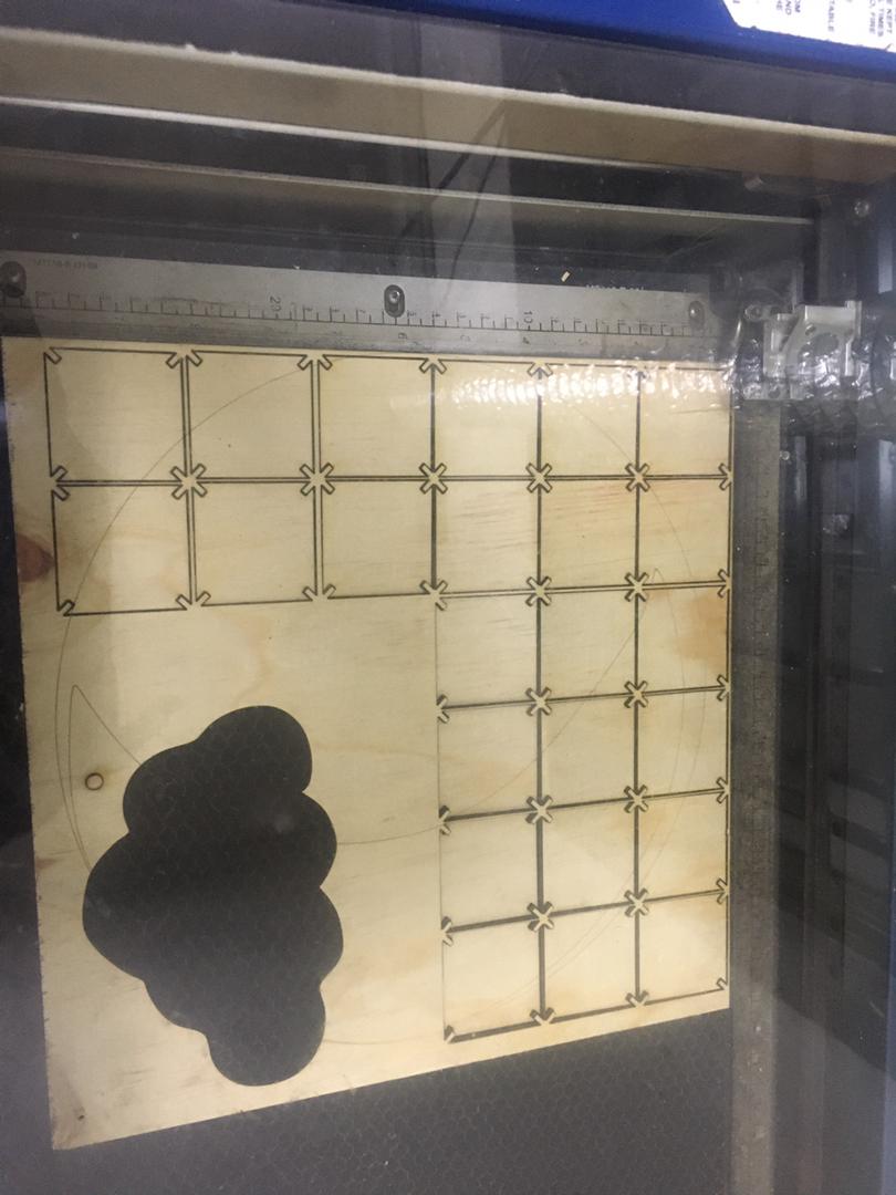
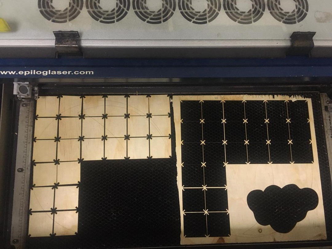
I multiplied and aligned pieces i had designed to be cut according to the piece of material i had, Set the power and speed, set focus on the material using this piece of metal that sets the distance between the nozzle and the material. so below are the pictures of the process of placing and after cutting the material in the laser.
Cutting and assembling
I placed the material to be cut which in this case is 3MM plywood sheet in the laser.
Assembling
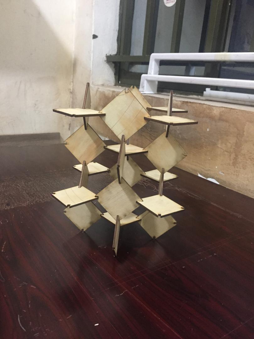
At first i assembled my pieces while putting together the joints vertically and horizontally
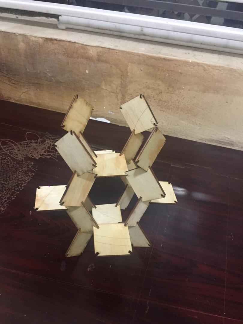
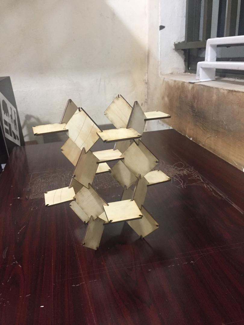
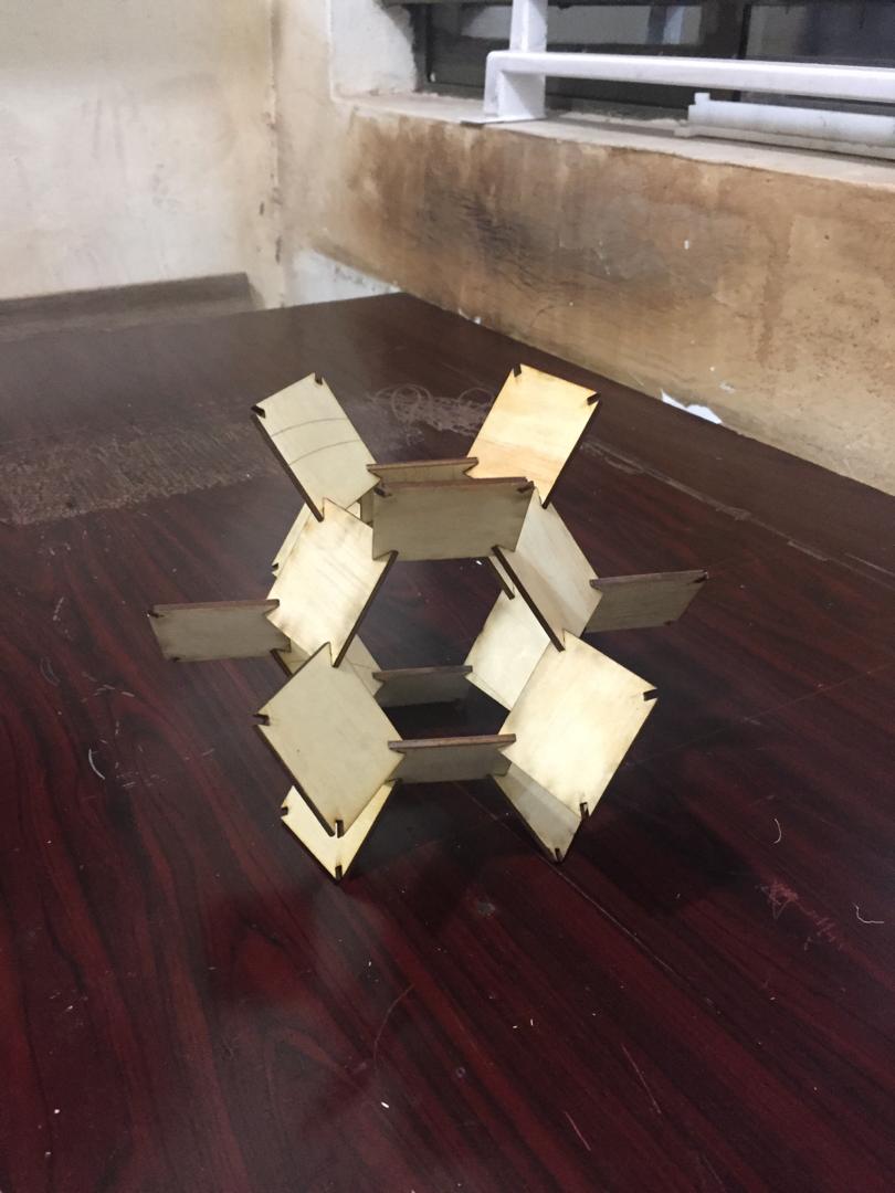
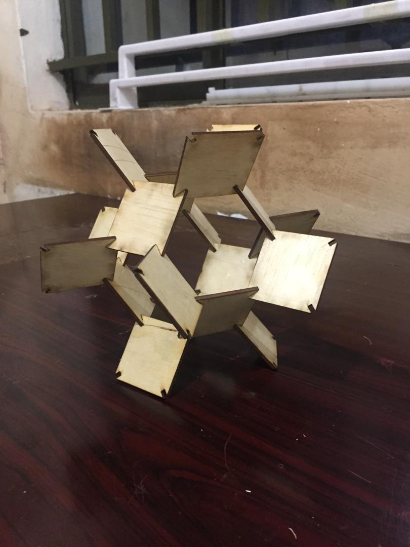
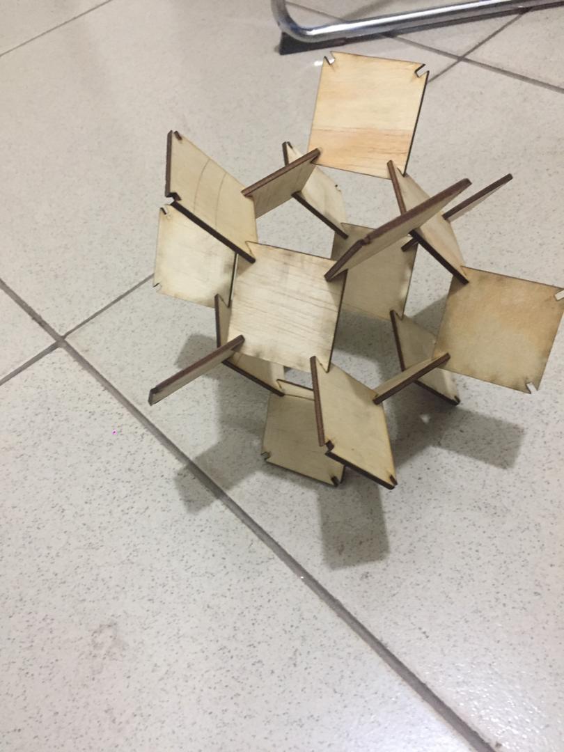
Then later i assembled these pieces while putting together the joints with pieces laying inclined or oblique to one anothe.
Assignment Files